LASER COMMUNICATION SYSTEM
hello friends today I am gonna telling you about some easy and valuable electronics projects for school and college practical
This laser communication system transmits sound or music signals through a laser beam. The intensity of the laser beam changes with the amplitude of the sound signal. The variation in the intensity of the laser beam is converted into a variation in the voltage level by using a solar panel. The voltage variation on the solar panel is amplified by a low-voltage audio power amplifier LM386 and reproduced by a speaker. The maximum output of audio amplifier LM386 is 1 watt, while its voltage gain is 20 to 200.
The circuit consists of a transmitter and a receiver. Both the transmitter and the receiver are built around IC LM386 , powered by a 9V battery
Fig . 1 shows the transmitter circuit . Here a laser diode ( LD1 ) with maxi mum operating voltage of around 2.6V DC and maximum operating current of 45 mA is used to transmit the audio signal . The voltage divider network formed by R2 , R3 and VR3 keeps the voltage as well as the current for the laser diode in the safe region .
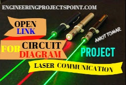
In place of the laser diode, you can also use a laser pointer. Remove the battery from the laser pointer. Extend two wires from terminals of LDI and connect them to the battery terminals of laser pointer . The spring inside the laser pointer is the negative terminal. The out put power of the laser pointer is 5 mW. Take care while working with laser , as direct exposure to the laser beam can be hazardous to your eyes. Point the laser beam to the solar panel.
Potmeter VR1 ( 10 - kilo - ohm ) is used to change the level of the input audio signal . The audio input ( Vin ) is taken from the preamplifier output of the music system ( CD player , DVD player , etc ) . Capacitor C2 and preset VR2 are used to vary the gain of the LM386 .
Fig. 2 shows the receiver circuit. The audio signal trans mitted by the laser diode ( LDI ) is received by the solar panel and amplified by IC2 . The gain of the amplifier is fixed by capacitor C7 . Preset VR4 is used to change the signal level from the solar panel. This signal is fed to input pin 3 of IC2 through coupling capacitor C5 so that the DC value from the solar panel can be eliminated . The amplified output from IC2 is panel fed to the speaker , which plays the mu sic from the CD player connected at the input ( Vin ) of IC1.
Assemble the transmitter and receiver circuits on separate PCBs and enclose in suitable cabinets . In the transmitter cabinet , fix two terminals for connecting the audio signal Fix switch S1 on the front panel and the laser diode ( LD1 or laser pointer ) to the rear side of the cabinet Keep the 9V battery inside the cabinetIn the receiver cabinet , fix the solar panel to the rear side such that the transmitted beam directly falls on it . Fix switch S2 on the front panel and the speaker to the rear side. Keep the 9V battery inside the cabinet. Refer Figs 3 and 4 for the laser pointer and solar panel.
After assembling both the circuits , orient the laser diode ( or laser pointer ) such that the transmitted laser beam directly falls on the solar panel . Use shielded wires for connecting to audio input and solar panel to reduce noise pickup .


0 comments:
Post a Comment