IR DETECTOR
hello friends today I am gonna telling you about some easy and valuable electronics projects
for school and college practical
Using this IR detector, you can check the functioning of remote handsets. It can also be used as the front end of IR-based receiver circuits. The detector uses photovoltaic property of the IR diode to detect IR radiations in the range of 30 cm to 50 cm.
HOME MADE IR DETECTOR

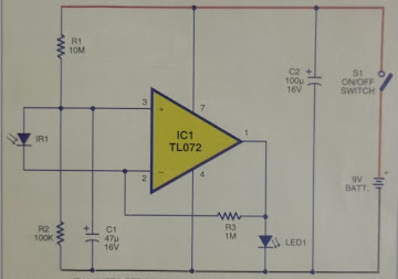
The gallium-arsenide p-n junction diode (IR1) can generate around 100µA current when exposed to a source of visible or infrared light. The current thus generated is proportional to the intensity of light falling on it. In the circuit, diode IR1 detects IR radiations and generates corresponding current,
which is amplified by a current-to-voltage converter built around IC TL071 (1C1), which is a low-noise JFET op-amp with low input voltage. The input offset current of TL071 is 2 nA and the input bias current is 7 nA. The non-inverting input of IC1 is connected to a potential divider comprising R1 and R2. High- value resistor R1 along with capacitor Cl keeps the non-inverting input stable for easy swing of output to high state.
 |
| IR DETECTOR CIRCUIT DIAGRAM |
Infrared detector diode IR1 is connected between the non-inverting and inverting input cathode toward the inverting input. resistor R3 perform the negative feedback function.
when the power is switched on through switch SI, LEDI lights up to indicate that the circuit is ready. It, however, gradually turns off as resistor R3 draws current from the output. The circuit then goes to the standby mode and maintains balance between the non-inverting and inverting inputs. At this stage, the output will remain low and LEDI 'off
. When the remote control handset is focused towards the detector diode and any of the buttons is pressed, the IR beam falls on IR1 to generate a cur- rent, which upsets the balance between non-inverting and inverting inputs of IC1. LEDI starts flashing to indicate the presence of IR beam that was coming from the remote handset.
Assemble the circuit on a general- purpose PCB and enclose in a suitable cabinet. Use a 9V PP3 battery to power the circuit. Black tubing is necessary for the IR diode since daylight may affect the functioning of the circuit.
friends please LIKE ,SHARE and FOLLOW thanks for your support


0 comments:
Post a Comment