TEMPERATURE-DEPENDET SPEED REGULATOR FOR FAN
hello friends today I am gonna telling you about some easy and valuable electronics projects
for school and college practical
This temperature-dependent controller for fan speed use an LM35 varies linearly
temperature sensor IC for precision sensing of the temperature
the output voltage of LM35 varies linearly with the temperature changes
in degrees celsius.
low output impedance , linear output variation with input changes and precise
inherent calibration of LM35 make interfacing of this device to read out or
control circuitry easy . LM35 exhibits extremely low self heating , as it draws
only 60μA from the power supply and operates over a wide temperature
range -55℃to +150 ℃.
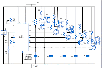
the output of LM35 is fed to LM3914, which senses the analogue voltage levels and
drive five relays. Each relay change the fan speed corresponding to the rise in temperature
as shown in table . the output pins of IC2 LM3914 are pulled high
(through 10-kilo -ohm resistors ) to Vcc.
IC2 contains its own adjustable reference and an accurate 10 step voltage divider network . the buffer drives ten individual comparators referenced to the precision potential divider
Only five out of the ten outputs of LM3914 are used here to drive PNP transistor T1through T5(eachBC557) .When the temperature increases, the output of sensor LM35 goes high. As a result, the output of IC2 go low one after range. calibration is done using VR1 as per the heat received by the sensor .
Normally, a manual fan regulator has five position. Here we have five relays corresponding to each regulator position along with resistance network. relay connection along with series resistor network of fan regulator are shown in diagram . At a particular temperature, a relay energises and its contacts connect the corresponding fan regulator resistor network to the AC supply. suppose you have calibrated it such that when the temperature reaches 25℃, pin 14 of IC2 goes low and relay RL1 energises. As a result the fan starts moving at the lowest speed . similarly, when the temperature reaches 29℃, pin 13 goes low relay RL2 energises and the fan starts moving at a higher speed than position 1 described in the table . this continues for position of RL3and RL4 too .
Finally ,when the sensor temperature reaches 39℃, pin 10 goes low to energise relay RL5.As a result, the fan starts moving at the maximum speed because in the position all the relay are energised and all the resistor in series with the regulator have been bypassed as shown in diagram
 |
| DIAGRAM 1 |
Assemble the circuit on a general purpose PCB and house in a suitable cabinet.
connect the relay contact to the regulator as shown diagram , shows the pin configuration of sensor LM35and PNP transistor BC557. Use a flexible wire to connect 12V regulated power supply to the assembled circuit and place it suitably near the fan regulator


Please sir I need explanation about design and construction of a microcontroller based digital micrometer screw gauge
ReplyDelete